arduino: Build a proximity sensor
If you have trouble reverse-parking in the tight terraced streets of northern England, why not build one of these?
Why do this?
- The Arduino is a great platform for experimentation and in this tutorial we will build a device that can react to our proximity.
Tools required:
- An Arduino – ideally an Uno, but the code will work on most types, such as the Leonardo.
- A large breadboard.
- An HC-SR04 ultrasonic sensor.
- 9 x 220Ω resistors (Colour code red red brown gold).
- 3 x red LED.
- 3 x yellow LED.
- 3 x green LED.
- Male-to-male jumper cables.
In the world of hobbyist electronics there are two big names: the Raspberry Pi and the Arduino. And while the Raspberry Pi has the largest share of the spotlight we should not forget the Arduino, which was the board to launch the Internet of Things back in the mid 2000s.
The Arduino is a small microcontroller board created in Italy to enable a low-cost method for artists to use electronics. The Arduino comes as a hardware platform with an accompanying software application used to program the board. Thanks to the Arduino there has been a big change to the programming landscape, with the barrier to physical computing projects such as home automation and robotics being broken down by this cheap and flexible platform.
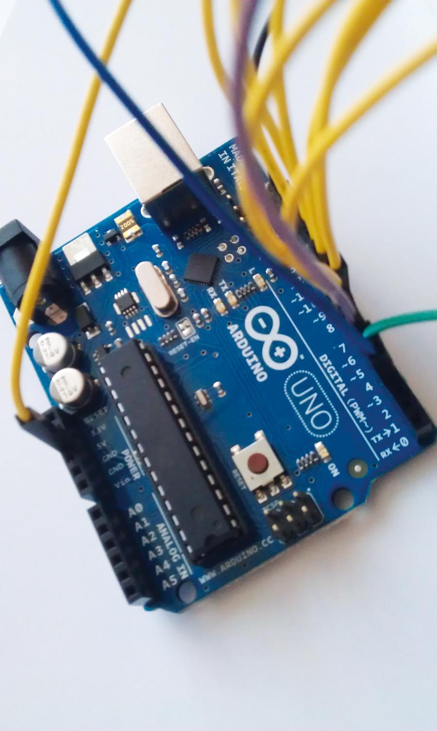
The Arduino platform encompasses a multitude of boards. Boards such as the Leonardo, Galileo and the Mega are available to purchase, but the most common board used by the majority of new hackers is the Uno. The Uno is a remarkable board that hits the sweet spot between functionality and price. It comes with 14 digital input/output pins and six analogue inputs all connected to a microcontroller in the form of the ATMEL ATmega328, which is programmed via a USB connection to your computer.
In this project we will be using an Arduino UNO R2, which is fully compatible with the newer Uno R3. Your Uno should also have a USB lead to connect to your computer. Insert one end into the Arduino and the other into your computer; can you see an LED labelled L13 on your board? This should be blinking, which is a test preloaded into every board to demonstrate that it is working.
Build your own distance sensor using just a few cheap components and a little bit of code.
Installing the Arduino software
The most convenient way to install the Arduino software is via the package manager for your distribution. For Debian- and Ubuntu-based systems type the following into a terminal, followed by the Enter key:
sudo apt-get install arduino
With the Arduino application installed we can now run it from the menu.
When run for the first time the Arduino application will ask for our current user to be added to a group called “dialout”. This is important as only members of this group can access the Arduino hardware that is attached to the USB port. Add your user to the dialout group and then close down all of your open applications, including the Arduino software, and log out of the current session. This will ensure that your user is added to the correct group and that their privileges are reloaded at the start of the new session. Once you’re logged in, open the Arduino application once more.
The Arduino Uno is a remarkable board and a great starting point for hardware hacking.
Arduino coding 101
The Arduino language is based upon a language called Processing, and is relatively easy to pick up especially if you have worked with languages such as Python before. Let’s step through an example provided by the Arduino team and one that is preloaded onto every Arduino.
In this example an LED attached to pin 13 blinks in an infinite loop. The Arduino Uno comes with a built-in LED for pin 13, labelled L13 on your board:
int led = 13;
void setup() {
pinMode(led, OUTPUT);
}
void loop() {
digitalWrite(led, HIGH);
delay(1000);
digitalWrite(led, LOW);
delay(1000);
}
We start by declaring a new variable, labelled as led, and in there we store the integer (int) value 13. With the variable created we now move to the setup section of our code and instruct the Arduino that the pin mode for our led pin is an output, which means that current will flow from the pin to the LED attached to it.
You can see that the code contained in void setup() and void loop() is contained inside {} brackets. Arduino uses these brackets to contain the code that belongs to that section, unlike Python, which uses indentation to denote what code belongs to what section. You will also notice that each line of code inside a section ends with a semi colon ‘;‘ this instructs the application that this line has been completed, and without them you will receive a compilation error.
Our focus shifts to the main body of code that will handle the blinking of our LED. This is contained in loop() and the blinking is achieved by sending power to the LED pin using digitalWrite(led, HIGH);. We then delay the program by one second and then turn off the power to the LED pin digitalWrite(led, LOW); and finally we delay the program by a further one second, effectively causing the blink. This is then looped infinitely.
This small piece of code is considered the “Hello World” of the Arduino platform, demonstrating the functionality in a simple manner. For our project we’re going to go much further, controlling nine LEDs via a novel input device.
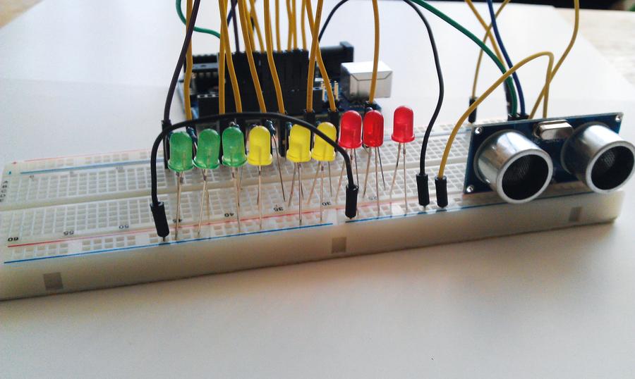
In our project we have nine LEDs attached to an Arduino via a series of wires and resistors that are connected via a breadboard. We have three green, yellow and red LEDs, which will provide a visual output when our ultrasonic sensor is triggered. An object 30 centimetres or further away will trigger the green LEDs, an object less than 30 centimetres but greater than 10 centimetres away will trigger the yellow LEDs. Finally an object less than 20cm away will trigger the red LEDs to illuminate warning us of a collision. This setup is very similar to a parking sensor.
So our logic would be as follows
Take a reading using the sensor.
If the distance is less than 10cm
Illuminate red LEDs
Else if the distance is greater than 10cm but less than 30cm
Illuminate the yellow LEDs
Else
Illuminate the green LEDs.
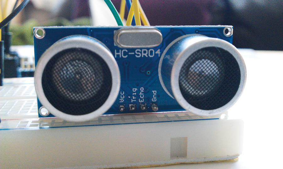
Ultrasonic sensors work by firing a burst of ultrasound
forwards. Any reflected ultrasound is bounced back to the
sensor enabling our code to calculate the distance.
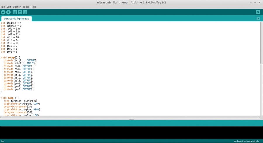
Creating variables
Unlike Python, the Arduino language requires us to identify the type of data that is being stored within a variable. In this case we’re storing the pin number for each of the components that are attached to the Arduino via a breadboard. This number is an integer, which is shortened to int. For this project we create 11 variables, nine that control each of the LEDs used and two that handle the sending and receiving of the ultrasonic pulse.
int trigPin = 4;
int echoPin = 3;
int red1 = 13;
int red2 = 12;
int red3 = 11;
int yel1 = 10;
int yel2 = 9;
int yel3 = 8;
int gre1 = 7;
int gre2 = 6;
int gre3 = 5;
In order to use the components connected to the Arduino, the Arduino has to be told that they are there, and to do that we need to provide instructions on where they are connected and what they will do. This is achieved via the void setup() configuration section, and in here we use pinMode to instruct the Arduino on what each pin will do. We earlier created a series of variables that store the pin locations for each of the components. We will use those with pinMode to identify the pin that we wish to configure. The configuration is quite simple: is the pin an input or an output? An input will wait for a signal/current from an external component, while an output will send a signal/current to an external component.
void setup() {
pinMode(trigPin, OUTPUT);
pinMode(echoPin, INPUT);
pinMode(red1, OUTPUT);
pinMode(red2, OUTPUT);
pinMode(red3, OUTPUT);
pinMode(yel1, OUTPUT);
pinMode(yel2, OUTPUT);
pinMode(yel3, OUTPUT);
pinMode(gre1, OUTPUT);
pinMode(gre2, OUTPUT);
pinMode(gre3, OUTPUT);
}
The void loop() is the our main body of code and contains the logic that controls the detection of an object by the ultrasonic sensor. We start the first part of this section by creating two variables, called duration and distance; these will contain long integers, so called because they have an extended size to store large numbers. We will use these variables to store the time taken for the pulse to be sent and received, and we shall use distance to store the answer to a calculation later in the code.
We next trigger a pulse to be sent from the ultrasonic sensor, but before we do that we must ensure that the ultrasonic sensor is not already transmitting. We do that using digitalWrite, which instructs the trigPin to change its state from on to off (HIGH to LOW).
The code then instructs the project to wait for two microseconds, which is just enough time for the ultrasonic sensor to settle ready for use.
We now use the digitalWrite function to send a pulse from the sensor by setting the trigPin to HIGH, in other words sending current to the sensor. Current is sent to the ultrasonic sensor for 10 microseconds using the delayMicroseconds() function. We then turn off the current to the trigPin, ending the pulse transmission sequence.
Now we need to do a little maths. To kick things off we record the time taken for the pulse to be sent and received, and this is stored in the duration variable that we created earlier. Lastly we use the distance variable to store the answer to the calculation, duration divided by 2, as we only need to know how long it took for the pulse to be received. The answer is then divided by 29.1 to give us the distance in centimetres:
void loop() {
long duration, distance;
digitalWrite(trigPin, LOW);
delayMicroseconds(2);
digitalWrite(trigPin, HIGH);
delayMicroseconds(10);
digitalWrite(trigPin, LOW);
duration = pulseIn(echoPin, HIGH);
distance = (duration/2) / 29.1;
For our last section of code we use the classic if, else if, else conditional statement to check for three different states. We’ll start with the if statement.
The first condition that we wish to test is to check the distance between the sensor and any objects that might be in the way. At this time we’re looking for objects less than 10 centimetres away, and if this condition is true we turn on the power to all of the red LEDs, and turn off the power to the yellow and green LED. This tells us that the object is really close, just like a parking sensor does in our cars:
if (distance < 10) {
digitalWrite(red1,HIGH);
digitalWrite(red2,HIGH);
digitalWrite(red3,HIGH);
digitalWrite(gre1,LOW);
digitalWrite(gre2,LOW);
digitalWrite(gre3,LOW);
digitalWrite(yel1,LOW);
digitalWrite(yel2,LOW);
digitalWrite(yel3,LOW);
}
Our next condition to check uses an else if statement, and this means that if the first if statement is false, check to see if this else if statement is now true and if so run the code. So if the distance between our sensor and object is greater than 10 centimetres but less than 30 centimetres, the red and green LEDs are turned off, and the yellow LED are turned on, indicating that we are getting closer to the object:
else if (distance > 10 and distance < 30) {
digitalWrite(yel1,HIGH);
digitalWrite(yel2,HIGH);
digitalWrite(yel3,HIGH);
digitalWrite(gre1,LOW);
digitalWrite(gre2,LOW);
digitalWrite(gre3,LOW);
digitalWrite(red1,LOW);
digitalWrite(red2,LOW);
digitalWrite(red3,LOW);
}
Our last condition to test is rather simple, as it does not require anything to test. else is used when all other conditions have been tested and proven to be false. If everything is false then else must be true. So if the object is not less than 10 centimetres away, or further than 30 centimetres away then the red and yellow LED will be turned off and the green LED will be turned on, indicating that we are far enough away from the sensor. Our last line of code controls the speed of the project and introduces a half-second delay before the main loop is repeated once again:
else {
digitalWrite(red1,LOW);
digitalWrite(red2,LOW);
digitalWrite(red3,LOW);
digitalWrite(gre1,HIGH);
digitalWrite(gre2,HIGH);
digitalWrite(gre3,HIGH);
digitalWrite(yel1,LOW);
digitalWrite(yel2,LOW);
digitalWrite(yel3,LOW);
}
delay(500);
}
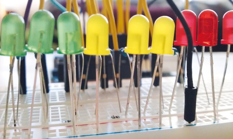
Our LEDs have their shortest leg in line with the ground rail of our breadboard and their longest leg in line with a resistor to lengthen their
lifespan.
Building the hardware
Arduino projects come as a package, with software and hardware. With the code already taken care of, our focus shifts to the hardware build of the project.
We start our build with the humble breadboard, and to the breadboard we add the HC-SR04 ultrasonic sensor, taking care to note the pin layout as we will need to connect each of those pins, using the breadboard to the relevant pins of the Arduino.
Here are the connections for the ultrasonic sensor:
VCC connects to 5V.
GND connects to GND (we will use the ground rail on the breadboard, marked with a “-”).
Echo connects to pin 3.
Trigger connects to pin 4
Now we just mentioned that we will use the ground rail on the breadboard. The rails are the outer two columns of holes that are marked “+” and “-”. Power, otherwise known as VCC or V+, is connected to the “+” rail, and ground, otherwise known as GND or V-, is connected to “-”. In this project we just use the “-”. By connecting the GND from our Arduino to the “-” rail via a jumper cable we create a common ground that any component can safely use.
With the sensor attached, now is the time to connect each of the 9 LEDs to our breadboard. LEDs come with two legs: the longest is the positive leg, commonly known as the Anode; and a shorter leg which is negative/ground and known as a Cathode. When connecting our LEDs to the breadboard, the cathode will be inserted into the same “-” (ground) rail that we used for the sensor. The longer anode leg needs to be inserted into the main breadboard area, so do this for all of the LEDs.
Our LEDs require a resistor in line from the Arduino to the LEDs. We need this to protect the LED from too much current, which can damage or shorten the life of our LEDs. For each of the LEDs use a 220Ω resistor that bridges the central channel and is in line with the LED anode leg. With the resistors inserted now grab some male-to-male jumper cables and wire to the Arduino as follows:
- Red1 = pin 13.
- Red2 = pin 12.
- Red3 = pin 11.
- Yellow1 = pin 10.
- Yellow2 = pin 9.
- Yellow3 = pin 8.
- Green1 = pin 7.
- Green2 = pin 6.
- Green3 = pin 5.
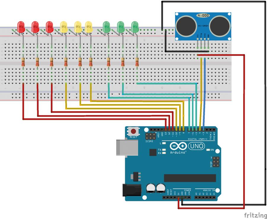
This diagram was created in Fritzing, a great tool to help you design the layout of a project. You can find a high resolution version in the repository for this project.
Before applying power double-check all of your connections; the worst thing that can happen is that an LED will pop, but checking your circuit is a good habit to get into. When ready, connect your Arduino to your computer via the USB lead and upload the code to your board via the upload button in the Arduino application. After about 10 seconds your project will come to life and you can move your hand in front of the sensor to trigger the different coloured LEDs. If the code does not auto start, press the reset button on your Arduino.
That’s it! You’ve built your very own distance sensor using less than £10 of parts and around 80 lines of code. You’re officially an electronics engineer!
You can find the complete code for this project at our GitHub https://github.com/lesp/LinuxVoice_Issue11_Arduino_Project or as a Zip file at https://github.com/lesp/LinuxVoice_Issue11_Arduino_Project/archive/master.zip
Related Posts


About The Author
Les Pounder
Les Pounder is a maker and hacker specialising in the Raspberry Pi and Arduino. Les travels the UK training teachers in the new computing curriculum and Raspberry Pi.